When an electronic component is powered, heat will be developed which will in turn increases the component
temperature. For safe functioning of these components manufacturer specifies allowable temperature. If the
component temperature exceeds these limits component fails. To get rid of this situation heat dissipation
mechanism must be effective. Thermal design of an enclosure for PCBs of a rack mountable unit is taken up in
this work.
The primary objective is to enhance the heat dissipation rate with the proposed enclosure in free and forced
convection environment. Selection of fan and estimation of cooling rate is also done. As part of the work
junction temperature is estimated using commercial Solid Works software package. After validation process
maximum component temperature is obtained in order to ascertain the cooling effectiveness of the proposed
thermal design by ensuring that maximum temperature is within the prescribed limits.
The selection of a cabinet, enclosure or other packaging for an electronic product presents the designer or
system integrator with a variety of choices, in addition to certain criteria that will be dictated by the
nature of the application.
Introduction
The effect of the heat developed is, raising the temperature of the component mounted on PCB. Each component
will have allowable temperature specified by the manufacturer crossing which will result into either
malfunctioning of the component or permanent failure of the component. As the total reliability of the
electronic enclosure is highly dictated by the component, a cooling mechanism is essentially required for an
electronic enclosure. Compared to other modes of heat transfer, forced convection means will provide faster
cooling rates.
This work deals with designing a cooling scheme for an electronic enclosure of a Rack Mountable Unit in free
convection environment as well as in forced convection environment.In the whole exercise estimation of
junction temperature is a tedious task as standard literature mentions about standard geometries like plate,
cylinder etc., but not for this kind of complex geometries like enclosures with PCBs.
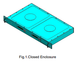
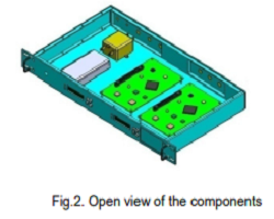
An analytical method is established during this work in which an expression for junction temperature is
used. This expression will be validated with that of evaluated using commercial SOLID WORKS software
package.The solid model of the electronic enclosure in assembled configuration is shown in Fig. 1 and 2.
Design Inputs
Number pf PCB’s = 2
Air Inlet Temperature = Ambient Temperature
Heat Load
ELEMENT
LOAD/HEAT(watts)
TSSOP
2
BGA 11,BGA 13
5
QFN
0.5
BGA 27
10
SOP
0.5
TQFP
1.5
Constraints
Analysis Type – Internal
Gravity - Along Z direction (-9.81 m/s2)
Project Fluid - Laminar and Turbulant
Project Solid - Aluminium 6061
Wall Condition - Adiabatic Wall
Pressure - 101325Pa
Velocity - 0 m/s (all the directions)
Initial Solid Temperature - 30°C
Relatve Humidity - 40%
Reference Temperature – 300°C
Thermal Analysis of Electronic Enclosure
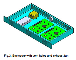
For appropriate analysis the given model cannot be used for flow analysis, in order to perform the analysis,
the given model needs to be an enclosed one. Hence the model is optimized. The enclosure consists of four
panels. Front, Rear, Left and Right. The front panel is inserted with vent holes and the rear panel is
inserted with an exhaust fan and is optimized as said before and is shown in fig.3.
The properties of the exhaust fan used is mentioned below
Property
Value
Name
PMD1238PKBX-A (2) (Pre-defined)
Fan Type
Axial
Reference density
1.2 kg/m3
Mass/Volume flow rate
Volume flow rate
Rotor speed
1570.7964 rad/s
Outer diameter
0.037999 m
Direction of rotation
Clockwise
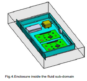
Further in order to specify the external conditions or the environment it is placed in, the enclosure is
kept in a fluid sub-domain with the specified constraints. Fig.4 shows the enclosure inside the fluid
sub-domain.
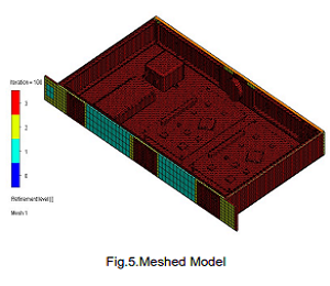
The next part of the analysis is to mesh the model. Finite Element Method reduces the degrees of freedom
from infinite to finite with the help of discretization or meshing (nodes and elements). One of the purposes
of meshing is to actually make the problem solvable using Finite Element.
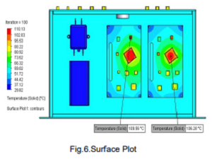
The meshed model is then run through the analysis with the required constraints and the surface plot is
obtained with the amount of heat dissipated from the individual components in the unit.
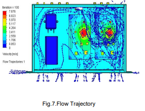
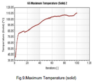
Figure.7. represents the floe trajectory of air flowing through the unit and also the heat carried by it.
After analysis we found out the maximum temperature is 110.13℃ as shown in the above figure. This also shows
the heat dissipation throughout the PCB.
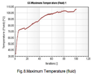
Further the two graphs indicate the maximum amount of heat carried out by the solid and fluid after certain
number of iterations and hence gives an idea about as to enhance or further modify the model.
Results and Summary
Maximum solid temperature in degree Celsius (°C) for all the different configurations with both Aluminium
enclosure and Magnesium enclosure is as following
Configuration Properties
Aluminium
Magnesium
Closed enclosure
131.68
131.21
Enclosure with Vent holes
118.62
118.96
Enclosure with exhaust fan
110.13
111.03
Enclosure with heat sink
89.09
84.09
Conclusion
As mentioned earlier the specified maximum temperature for the safe functioning of the rack mountable unit
is 120°C.From the analysis we can see that the maximum amount of heat is dissipated by using heat sink
ie., the thermal pad along with vent holes and exhaust fan. But practically it is not possible due to the
increase in power consumption and also makes the model more complicated. Hence we conclude that it is best
suited to use the enclosure with vent holes as it ensures the required amount of heat dissipation to keep
the unit safe.
From the analysis on using alternative material that is magnesium we find that there is a bit more heat lost
but not much difference when compared with aluminium. When the two materials are compared with respect to
other properties aluminium has better heat conductivity and better machinability and has a thermal
conductivity of 205 W/mK whereas magnesium has lower weight density and is brittle in nature with a thermal
conductivity of 156 W/mK. Hence we conclude that Aluminium is best suited for the manufacturing of the RACK
MOUNTABLE UNIT.
Reference
P Rada, P bowler et al. Proceedings of the ASME 2011 Pacific Rim Technical Conference & Exposition on
Packaging and Integration of Electronic and Photonic Systems InterPACK2011 July 6-8, 2011, Portland, USA.
KunLi, Lianfa Yang et al. Advanced Materials Research Online: 2012-06-14
B.Raja et al. Int. Journal of Engineering Research and ApplicationsNovember 2015.
Anjaiah Madarapu, Murali Mohan Raju.T et al. IOSR Journal of Mechanical and Civil Engineering (2012)